
Cart is empty
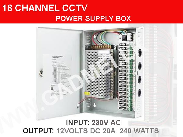

18 CHANNEL POWER SUPPLY CCTV CAMERA DISTRIBUTION POWER SUPPLY BOX - DC 12V 20A 240W OUTPUT
Special Price LKR 15000.00
Regular Price:
- Islandwide Delivery Available
18-CHANNEL POWER SUPPLY CCTV CAMERA DISTRIBUTION POWER SUPPLY
DC 12 Volts, 20 Amps, 240 Watts OUTPUT
Professional, high-capacity distributed power supply unit, specifically designed for CCTV camera security systems and other applications requiring multiple centralized 12V DC power connections.
It acts as a single central hub to power up to 18 individual devices, eliminating the need for multiple separate wall adapter plugs. The system converts high-voltage AC mains power (like from a standard wall outlet) into safe, low-voltage 12V DC power required by security cameras, LED strips, or access control systems.
-
Centralized Distributed Power: Can power 18 separate channels from one single box. This greatly simplifies wiring and organization in server racks or security control rooms.
-
Fused Individual Channels: Each of the 18 outputs is individually fused (using reset-able PTC fuses or standard glass fuses, which are visible near the output terminal block).
-
If one camera develops a short circuit, its fuse will pop, protecting that channel and preventing the entire system or other cameras from going down.
-
Adjustable Output Voltage: The DC output voltage can be adjusted between 12V and 14V. This is a crucial feature for compensating for voltage drops over very long cable runs, ensuring the camera at the far end still receives a full 12V.
-
Dual-Voltage Input Capability: The system can be manually switched to work with either 110-120V (common in North America) or 220-240V (common in Europe/Asia) standard AC power, making it globally compatible.
-
(Note: The switch inside must be set correctly for your region).
-
Visual Monitoring: Features a master LED power indicator to show the unit is on and often has individual LED indicators for each channel to verify that power is flowing to every connected camera.
-
Heavy-Duty Metal Enclosure:
-
Housed in a sturdy, lockable metal box, which provides physical protection and can be wall-mounted for organized installation.
-
It also serves as a heat sink to help cool the internal electronics.
| Model Type | Distributed Switching Power Supply (SMPS) |
| Total Power Output | 220 Watts |
| AC Input Voltage |
200-240 Vac |
| AC Input Frequency | 50Hz or 60Hz |
| DC Output Voltage (Default) | 12V DC |
| Adjustable DC Voltage Range | 12V to 14V DC |
| Total Current Output |
Approx. 18 Amps (Total) (Based on 220W / 12V ≈ 18.3A) |
| Number of Output Channels | 18 |
| Maximum Load per Channel | 1 Amp (Max) |
| Minimum Load per Channel | 0 Amps |
| Protection Type | Channel-specific Fused Outputs (PTC or Glass fuses) |
| Output Type | Screw Terminal Block (V+ and V-) for easy wire connection |
| Operating Environment Note | Requires "good ventilation" to prevent overheating. |
Recommended Applications
This unit is ideal for:
-
Multi-camera CCTV security system installations.
-
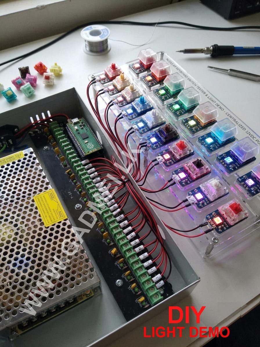
Powering multiple 12V LED light strips.
-
Centralized power for access control panels and electronic door locks.
-
Network racks requiring several individual low-power 12V feeds.
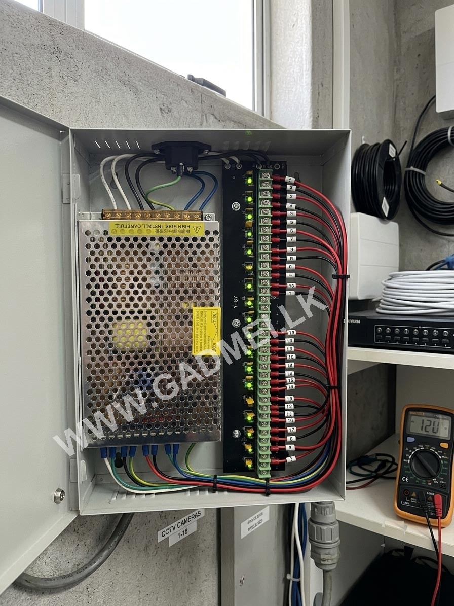
220W 12VDC 18-OUTPUT CCTV POWER SUPPLY
Input Characteristics:
-
AC Input Voltage & Frequency: 100-120/200-240 Vac.
-
The input frequency will be 50 or 60 (Hz).
-
Note: The input voltage can be chosen between 110Vac and 220Vac.
Output Characteristics:
-
Output Voltage: 12V DC
-
Voltage Range: 12V–14V DC
-
Maximum Current per Output (OUT1~OUT18): 1A
-
Minimum Load: 0A
General Notes:
-
Requires good ventilation.
⚠️ CRITICAL SAFETY WARNINGS - PLEASE READ FIRST ⚠️
-
DANGER: SHOCK HAZARD. Installation requires connecting high-voltage AC mains power (110V/220V). Do not attempt this unless you have electrical experience.
-
CONFIRM VOLTAGE SELECTOR: The manual states the unit can operate at 110-120V or 200-240V. You MUST verify and set the internal input switch to match your local power standard BEFORE plugging it in. Running a unit set to 110V on a 220V outlet will immediately destroy it and create a severe fire hazard.
-
DISCONNECT POWER: Never work on this unit while it is plugged in or connected to live mains power.
-
FUSE PROTECTION: Ensure the individual outputs are fused. (The green terminal block area has spaces for fuses).
-
VENTILATION: The manual explicitly notes: "The power supply requires good ventilation." Do not install it in a completely sealed, unventilated space.
Overview of Key Components
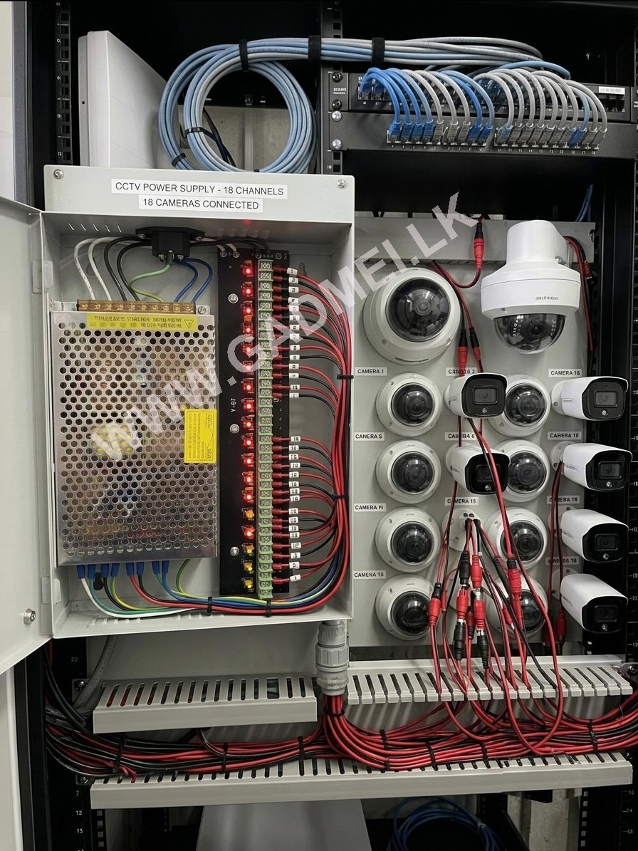
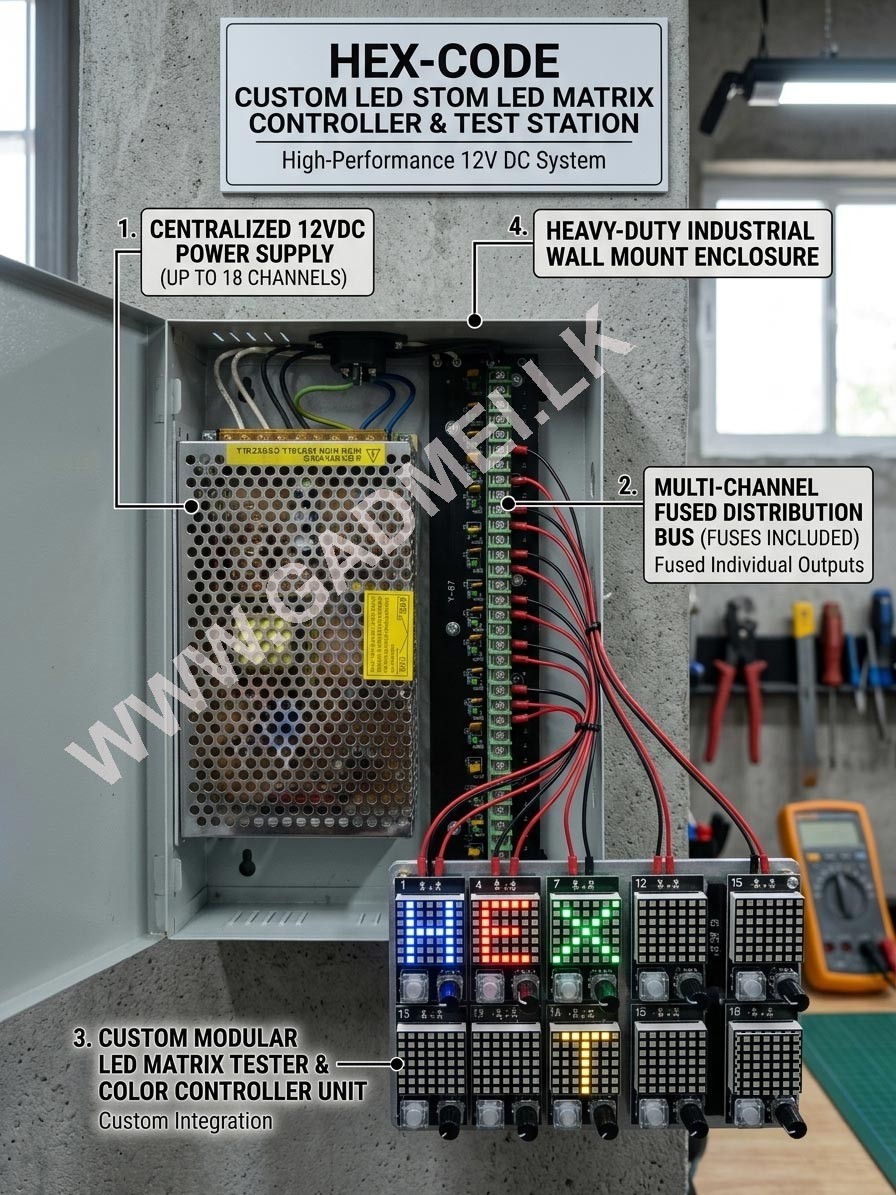
Based on image_0.png and image_1.png, identify these main areas inside the cabinet:
-
Main Power Brick: The silver mesh unit on the left.
-
AC Power Input Socket: At the top of the cabinet (black IEC-style inlet, likely for a standard "computer" power cord).
-
DC Output PCB: The black circuit board on the right with the 18-port green screw terminal blocks.
-
Wiring Harnesses:
-
AC Input:Often White (Neutral) and Black (Live/Hot) and Green (Ground/Earth) from the AC socket to the power brick. Verify your wire colors match your local electrical code. -
DC Output:The thicker blue and green wires connecting the silver power brick's V- and V+ outputs to the top of the black distribution PCB.
-
Step-by-Step Installation Guide
Select the AC Input Voltage:
-
-
Inspect the side or bottom of the silver power brick inside the cabinet. You should see a small red slide switch marked "on"
115V / 230Vor similar. -
CRITICAL: Set this switch to match the voltage of your wall outlet. (e.g.,
115Vfor the US/Canada;230Vfor the UK/Europe/Asia).
-
-
Connect the AC Mains Input (if not prewired):
-
If your unit came pre-wired to the internal AC socket (as shown in the image), skip to Step 3.
-
If you are hardwiring a power cord, locate the
L(Live/Hot),N(Neutral), andGND(Earth/Ground) terminals on the black socket at the top or on the internal silver brick (they should be clearly labeled). -
Strip your incoming power cord wires.
-
Connect them:
-
Green or green/yellow wire to
GND. -
White (or blue in Europe) wire to
Nneutral. -
Black (or brown in Europe) wire to
Llive.
-
-
Tighten all screws securely.
-
-
Mount the Cabinet:
-
Hold the empty metal box against the wall at your desired installation height (ensure there is room for ventilation above and around it).
-
Mark the wall through the keyhole mounting slots on the back of the case.
-
Drill pilot holes, install wall anchors (if needed), and secure the cabinet to the wall with appropriate screws.
-
Part 2: Configuring the Outputs
-
Connect Your Cameras/Devices:
-
Locate the green terminal blocks on the right side of the cabinet (numbered 1 through 18).
-
You will see two screws for each port. They are likely labeled as
V+(Voltage Positive) andV-(Voltage Negative/Ground. Double-check the labeling on the PCB itself or your specific schematic. The schematic shows 18 separate outputs. -
Each camera/device will have two power wires (e.g., red for '+' and black for '-').
-
Port 1: Strip the camera wires, connect red to
V+, and black toV-. Tighten the screws. Repeat for Ports 2 through 18 as needed. Keep wires organized.
-
-
Install the Fuses:
-
THIS UNIT MUST BE FUSED. There are spots on the PCB just to the left of the green terminals to insert individual fuses for each camera (standard glass barrel fuses, often 1A-2A rated, as mentioned in the manual
OUT1~OUT18 1A Max). Fuses protect individual cameras and prevent a single failure from shutting down the entire system. -
Insert a fuse of the correct rating (1A is standard for many cameras) into the fuse holder for each active channel.
-
Part 3: Power Up & Adjustment
-
Initial Power On (Cameras Disconnected is Safer):
-
Ensure all output switches (if the black distribution board has any master ON/OFF switches) are set to OFF.
-
Ensure no wires are touching or shorting.
-
Plug the standard AC power cord into the AC input socket at the top of the cabinet and then into a live wall outlet.
-
The internal power brick's LED indicator (often green) should illuminate.
-
-
Verify the Output Voltage:
-
Use a multimeter set to measure DC voltage.
-
Measure the voltage at one of the
V+andV-pairs on the distribution terminal block. It should read approximately 12V DC.
-
-
Adjust the Voltage (If Necessary):
-
On the front of the silver power brick, locate the adjustment potentiometer (a small plastic screw, likely yellow or blue, labeled
+V ADJor similar, visible just below the large yellow high-risk sticker). -
If you have very long cable runs (e.g., over 100ft), the voltage at the far end will drop. Turn the adjustment screw with a small screwdriver to slightly increase the voltage (the range is 12V-14V DC). Check the voltage at the distribution block—do not set it excessively high, as it may damage shorter-run cameras. A setting of ~13.5V can often compensate for average long runs.
-
-
Complete the System:
-
Turn on the master DC output switches on the distribution board (if equipped). The individual camera/channel LEDs should turn green, indicating power is flowing to each device.
-
Verify the cameras are now powered and sending a video signal to your recording device.
-
-
Final Check: Securely close and lock the metal cabinet door. Ensure the ventilation slots on the top and sides of the cabinet are clear.
⚠️ SAFETY WARNINGS:
-
"HIGH RISK INSTALL CAREFULLY": As seen on the yellow sticker, installing this unit involves working with high-voltage AC mains power. Installation by a qualified electrician or licensed professional is strongly recommended.
-
Input Voltage Selector: The manual clearly states, "The input voltage can be chosen between 110 Vac and 220 Vac." The user MUST manually set the internal input selector switch (often on the side or bottom of the internal silver mesh power brick) to match their local wall outlet voltage (e.g., set to 110V for the USA) BEFORE plugging it in. Failing to do so will destroy the unit and create a fire hazard.
-
Ventilation: The label notes: "The power supply requires good ventilation." Do not install it inside a tiny, sealed, unventilated cabinet where heat can build up, as this can lead to premature failure or a fire.